14 KiB
Overview
On this page, you'll find detailed instructions on how to wire the module of a Wemos D1 mini or ESP32 to the radio module, as well as how to flash it with the latest firmware. This information will enable you to communicate with compatible inverters.
You find the full User_Manual here
Compatiblity
The following inverters are currently supported out of the box:
Hoymiles Inverters
| Status | Serie | Model | comment |
|---|---|---|---|
| ✔️ | MI | 300, 600, 1000/1200/⚠️ 1500 | 4-Channel is not tested yet |
| ✔️ | HM | 300, 350, 400, 600, 700, 800, 1000?, 1200, 1500 | |
| ⚠️ | TSUN | TSOL-M350, TSOL-M400, TSOL-M800/TSOL-M800(DE) | others may work as well (need to be verified). |
Table of Contents
- Table of Contents
- Overview
- Compatiblity
- Things needed
- Wiring things up
- Flash the Firmware on your Ahoy DTU Hardware
- Connect to your Ahoy DTU
- MQTT command to set the DTU without webinterface
- Used Libraries
- ToDo
Solenso Inverters:
- SOL-H350
Things needed
If you're interested in building your own AhoyDTU, you'll need a few things to get started. While we've provided a list of recommended boards below, keep in mind that the maker community is constantly developing new and innovative options that we may not have covered in this readme..
For optimal performance, we recommend using a Wemos D1 mini or ESP32 along with a NRF24L01+ breakout board as a bare minimum. However, if you have experience working with other ESP boards, any board with at least 4MBytes of ROM may be suitable, depending on your skills.
Just be sure that the NRF24L01+ module you choose includes the "+" in its name, as we rely on the 250kbps features that are only provided by the plus-variant.
| Parts | Price |
|---|---|
| D1 ESP8266 Mini WLAN Board Microcontroller | 4,40 Euro |
| NRF24L01+ SMD Modul 2,4 GHz Wi-Fi Funkmodul | 3,45 Euro |
| 100µF / 10V Capacitor Kondensator | 0,15 Euro |
| Jumper Wire Steckbrücken Steckbrett weiblich-weiblich | 2,49 Euro |
| Total costs | 10,34 Euro |
If you're interested in using our sister project OpenDTU or you want to future-proof your setup, we recommend investing in an ESP32 board that features two CPU cores. As Radio you can also use a NRF24L01+ module with an external antenna. While this option may cost a bit more, it will provide superior performance and ensure compatibility with upcoming developments.
| Parts | Price |
|---|---|
| ESP32 Dev Board NodeMCU WROOM32 WiFi | 7,90 Euro |
| NRF24L01+ PA LNA SMA mit Antenne Long | 4,50 Euro |
| 100µF / 10V Capacitor Kondensator | 0,15 Euro |
| Jumper Wire Steckbrücken Steckbrett weiblich-weiblich | 2,49 Euro |
| Total costs | 14,89 Euro |
There are fake NRF24L01+ Modules out there
Watch out, there are some fake NRF24L01+ Modules out there that seem to use rebranded NRF24L01 Chips (without the +).
An example can be found in Issue #230.
You are welcome to add more examples of faked chips. We will add that information here.
Some users reported better connection or longer range through more walls when using the "E01-ML01DP5" EBYTE 2,4 GHz Wireless Modul nRF24L01 + PA + LNA RF Modul, SMA-K Antenna connector, which has an eye-catching HF cover. But beware: It comes without the antenna!
In any case you should stabilize the Vcc power by a capacitor and don't exceed the Amplifier Power Level "LOW". Users reporting good connection over 10m through walls / ceilings with Amplifier Power Level "MIN". It is not always the bigger the better...
Power levels "HIGH" and "MAX" are meant to wirings where the nRF24 is supplied by an extra 3.3 Volt regulator. The bultin regulator on ESP boards has only low reserves in case WiFi and nRF are sending simultaneously. If you operate additional interfaces like a display, the reserve is again reduced.
Wiring things up
The NRF24L01+ radio module is connected to the standard SPI pins:
- SCLK (Signal Clock),
- MISO (Master In Slave Out) and
- MOSI (Master Out Slave In)
These pins need to be configured in the config.h.
Additional, there are 3 pins, which can be set individual:
- CS (Chip Select),
- CE (Chip Enable) and
- IRQ (Interrupt)
These pins can be changed from the /setup URL.
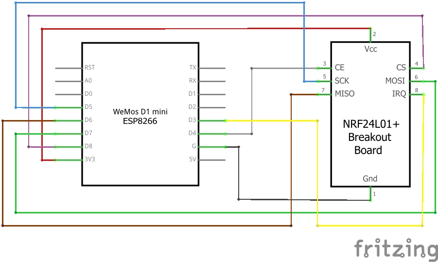
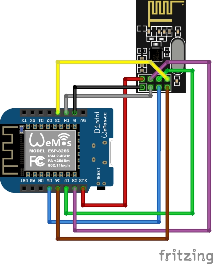
ESP8266 wiring example on WEMOS D1
This is an example wiring using a Wemos D1 mini.
Schematic
Symbolic view
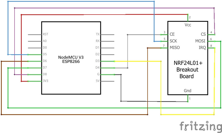
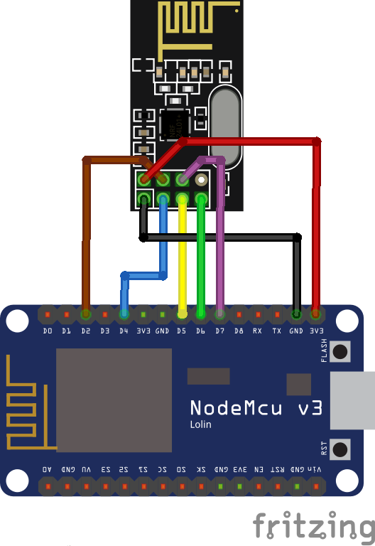
ESP8266 wiring example on 30pin Lolin NodeMCU v3
This is an example wiring using a NodeMCU V3.
Schematic
Symbolic view
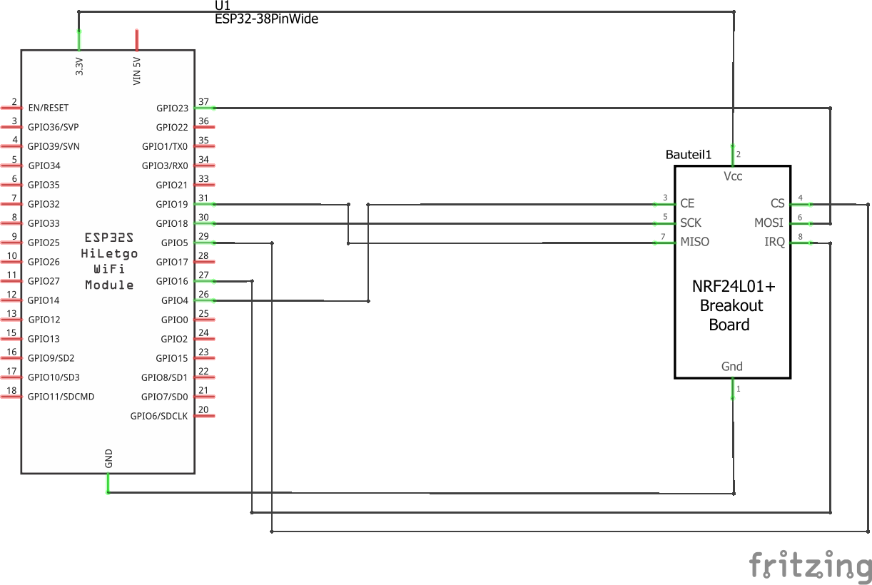
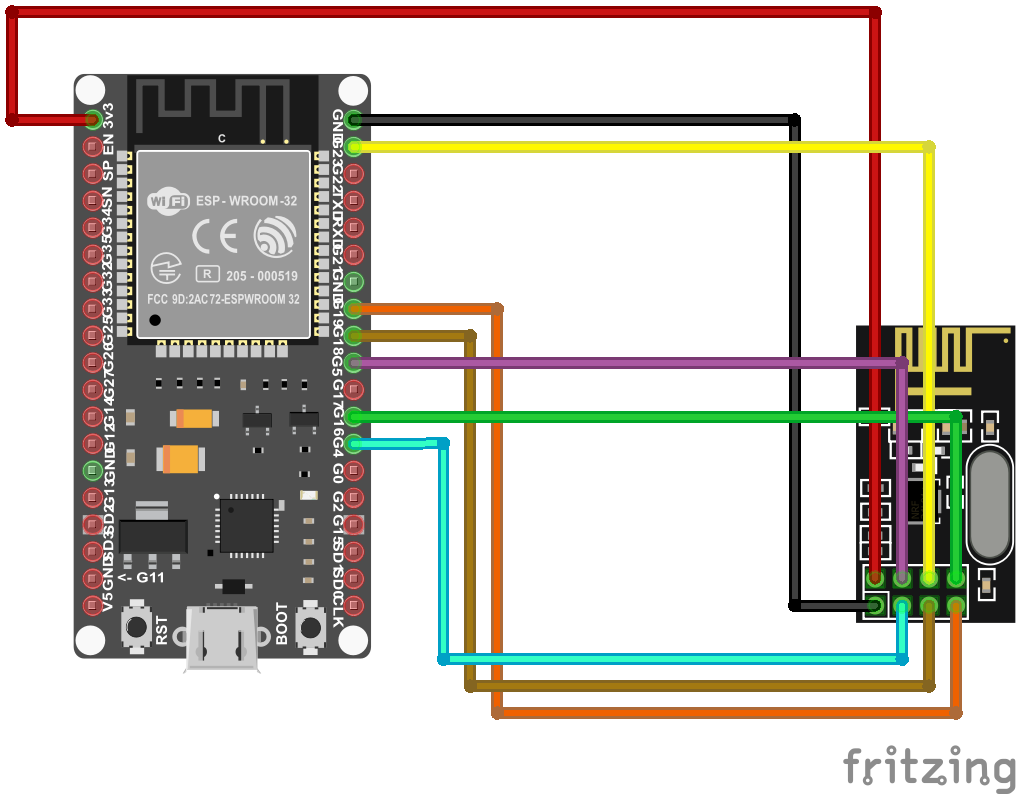
ESP32 wiring example
Example wiring for a 38pin ESP32 module
Schematic
Symbolic view
ESP32 GPIO settings
CS, CE, IRQ must be set according to how they are wired up. For the diagram above, set the 3 individual GPIOs under the /setup URL as follows:
CS   D1 (GPIO5)
CE   D2 (GPIO4)
IRQ  D0 (GPIO16 - no IRQ!)
IMPORTANT: From development version 108/release 0.6.0 onwards, also MISO, MOSI, and SCLK are configurable. On new installations, their defaults are correct for most ESP32 boards. These pins cannot be configured for ESP82xx boards, as this chip cannot move them elsewhere.
If you are upgrading an existing install though, you might see that these pins are set to '0' in the web GUI. Communication with the NRF module wont work. For upgrading an existing installations, set MISO=19, MOSI=23, SCLK=18 in the settings. This is the correct default for most ESP32 boards. On ESP82xx, simply saving the settings without changes should suffice. Save and reboot.
Flash the Firmware on your Ahoy DTU Hardware
Once your Hardware is ready to run, you need to flash the Ahoy DTU Firmware to your Board. You can either build your own using your own configuration or use one of our pre-compiled generic builds.
Flash from your browser (easy)
The easiest step for you is to flash online. A browser MS Edge or Google Chrome is required. Here you go
Compiling your own Version
This information suits you if you want to configure and build your own firmware.
This code comes to you as a PlatformIO project and can be compiled using the PlatformIO Addon.
Visual Studio Code, AtomIDE and other IDE's support the PlatformIO Addon.
If you do not want to compile your own build, you can use one of our ready-to-flash binaries.
Optional Configuration before compilation
- number of supported inverters (set to 3 by default)
config.h - DTU radio id
config.h(default = 1234567801) - unformatted list in webbrowser
/livedataconfig.h,LIVEDATA_VISUALIZED
Alternativly, instead of modifying config.h, config_override_example.h can be copied to config_override.h and customized.
config_override.h is excluded from version control and stays local.
Using a ready-to-flash binary using nodemcu-pyflasher
This information suits you if you just want to use an easy way.
- download the flash-tool nodemcu-pyflasher
- download latest release bin-file from ahoy_
- open flash-tool and connect the target device to your computer.
- Set the correct serial port and select the correct *.bin file
- click on "Flash NodeMCU"
- flash the ESP with the compiled firmware using the UART pins or
- repower the ESP
- the ESP will start as access point (AP) if there is no network config stored in its eeprom
- connect to the AP (password:
esp_8266), you will be forwarded to the setup page - configure your WiFi settings, save, repower
- check your router or serial console for the IP address of the module. You can try ping the configured device name as well.
Once your Ahoy DTU is running, you can use the Over The Air (OTA) capabilities to update your firmware.
! ATTENTION: If you update from a very low version to the newest, please make sure to wipe all flash data!
Connect to your Ahoy DTU
When everything is wired up and the firmware is flashed, it is time to connect to your Ahoy DTU.
Your Ahoy DTU is very verbose using the Serial Console
When connected to your computer, you can open a Serial Console to obtain additional information.
This might be useful in case of any troubles that might occur as well as to simply
obtain information about the converted values which were read out of the inverter(s).
Connect to the Ahoy DTU Webinterface using your Browser
After you have sucessfully flashed and powered your Ahoy DTU, you can access it via your Browser.
If your Ahoy DTU was able to log into the configured WiFi Network, it will try to obtain an IP-Address
from your local DHCP Server (in most cases thats your Router).
In case it could not connect to your configured Network, it will provide its own WiFi Network that you can
connect to for furter configuration.
The WiFi SSID (the WiFi Name) and Passwort is configured in the config.h and defaults to the SSID "AHOY-DTU" with the Passwort "esp_8266".
The Ahoy DTU will keep that Network open for a certain amount of time (also configurable in the config.h and defaults to 60secs).
If nothing connects to it and that time runs up, it will retry to connect to the configured network an so on.
If connected to your local Network, you just have to find out the used IP Address or try the default name http://ahoy-dtu/. In most cases your Router will give you a hint.
If you connect to the WiFi the Ahoy DTU opens in case it could not connect to any other Network, the IP-Address of your Ahoy DTU is http://192.168.4.1/.
Just open the IP-Address in your browser.
The webinterface has the following abilities:
- OTA Update (Over The Air Update)
- Configuration (Wifi, inverter(s), NTP Server, Pinout, MQTT, Amplifier Power Level, Debug)
- visual display of the connected inverters / modules
- some statistics about communication (debug)
HTTP based Pages
To take control of your Ahoy DTU, you can directly call one of the following sub-pages (e.g. http://ahoy-dtu/setup or http://192.168.4.1/setup ).
| page | use | output | default availability |
|---|---|---|---|
| /uptime | displays the uptime uf your Ahoy DTU | 0 Days, 01:37:34; now: 2022-08-21 11:13:53 | yes |
| /reboot | reboots the Ahoy DTU | yes | |
| /erase | erases the EEPROM | yes | |
| /factory | resets to the factory defaults configured in config.h | yes | |
| /setup | opens the setup page | yes | |
| /save | yes | ||
| /cmdstat | show stat from the home page | yes | |
| /visualization | displays the information from your converter | yes | |
| /livedata | displays the live data | yes | |
| /json | gets live-data in JSON format | json output from the livedata | no - enable via config_override.h |
| /metrics | gets live-data for prometheus | prometheus metrics from the livedata | no - enable via config_override.h |
| /api | yes |
MQTT command to set the DTU without webinterface
Used Libraries
| Name | version | License |
|---|---|---|
ESP8266WiFi |
1.0 | LGPL-2.1 |
DNSServer |
1.1.1 | LGPL-2.1 |
SPI |
1.0 | LGPL-2.1 |
Hash |
1.0 | LGPL-2.1 |
EEPROM |
1.0 | LGPL-2.1 |
ESP Async WebServer |
1.2.3 | LGPL-3.0 |
ESPAsyncTCP |
1.2.2 | LGPL-3.0 |
Time |
1.6.1 | LGPL-2.1 |
RF24 |
1.4.5 | GPL-2.0 |
PubSubClient |
2.8 | MIT |
ArduinoJson |
6.19.4 | MIT |
ESP Async WebServer |
4.3.0 | ? |